- Mechanical Engineering Drawing Symbols And Abbreviations
- Mechanical Engineering Drawing Symbols And Meanings
Tips to Model the parts on this page:
Mechanical Engineering Drawing Symbols And Abbreviations
1. Always use the chamfer feature instead of revolve cut.
2. When features are connecting to each other, always use surfaces to define the limit instead of a definites length or the value. This will help you while redesigning the part in the future.
3. As a learner, do try to visualize the parts using just 2D views. This will help you develop the thought process and will make it easier to understand all kinds of models and drawings.
4. Do not model, fillets/rounds in the sketcher itself. Always use a separate round feature.


Mechanical Engineering Drawing Symbols And Meanings
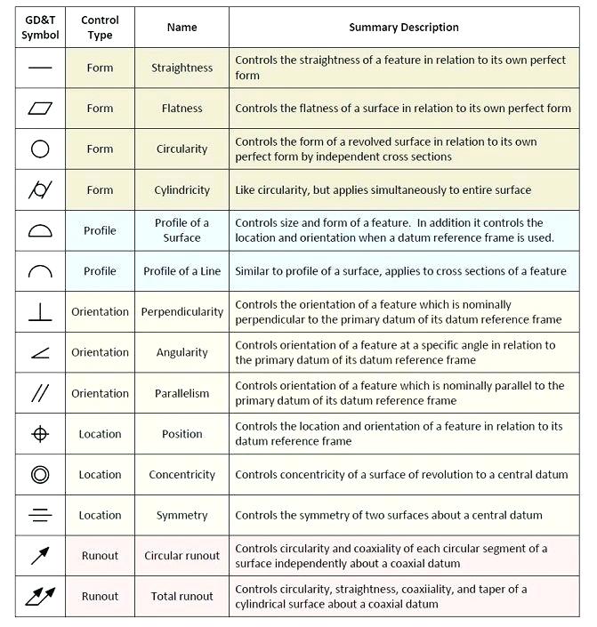
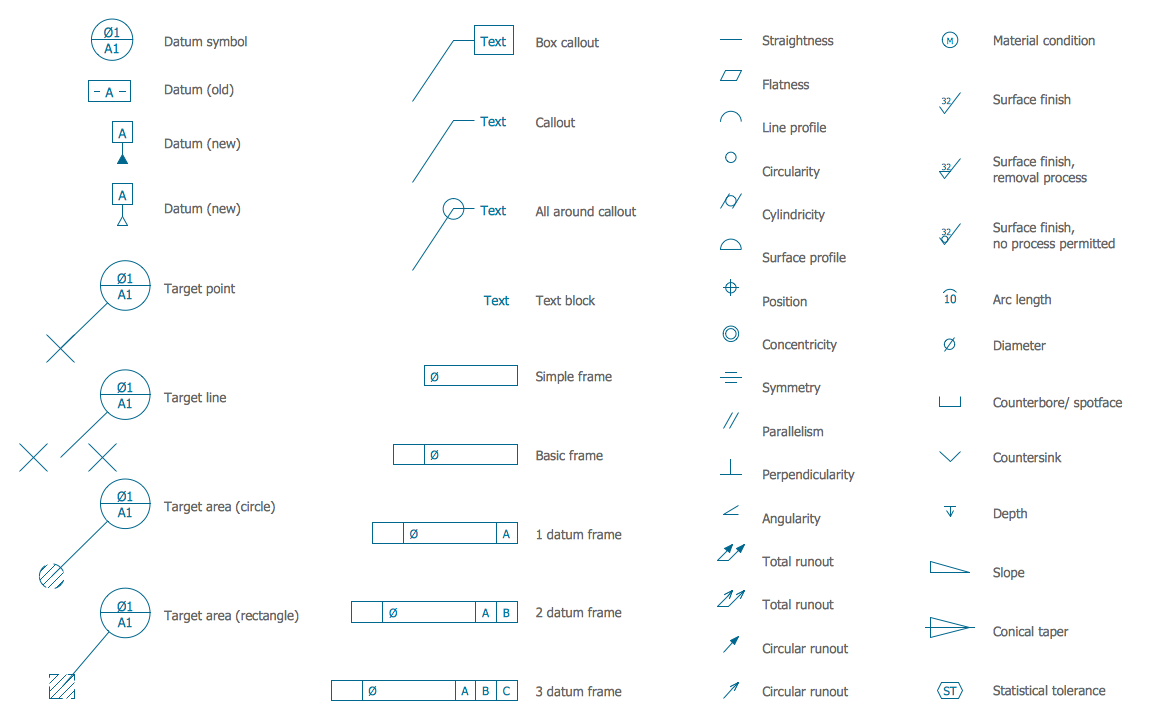
Basic types of symbols used in engineering drawings are countersink, counterbore, spotface, depth, radius, and diameter. Here are more commonly used engineering drawing symbols and design elements as below. You can also check out the GD&T symbols and terms on our site. 1.2 STATE how the grid system on an engineering drawing is used to locate a piece of equipment. 1.3 STATE the three types of information provided in the revision block of an engineering drawing. 1.4 STATE the purpose of the notes and legend section of an engineering drawing. 1.5 LIST the five drawing categories used on engineering drawings.